Animation 4: Inverse kinematics
Mohamad's interest is in Programming (Mobile, Web, Database and Machine Learning). He is studying at the Center For Artificial Intelligence Technology (CAIT), Universiti Kebangsaan Malaysia (UKM).
[1] Introduction
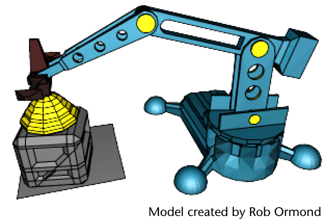
Inverse Kinematics (IK) allows you to efficiently pose your models and characters for animation. You pose the skeleton by positioning IK handles, usually located at the end of an IK joint chain (for example at the hand). The rotations for the other joints are calculated automatically by an IK solver. An IK solver calculates the rotations of each joint back up the hierarchy of the joint chain based on the position of the IK handle. See Creating a skeleton hierarchy for more information on skeletons and joints.
By contrast, Forward Kinematics (FK) requires you to rotate each joint in turn until you have the desired pose for a keyframe. This can be a tedious process when posing a complex skeleton. When using Inverse Kinematics, it’s faster to pose a character because the joint rotations further up the hierarchy are calculated automatically based on the placement of the IK Handle. Using both FK and IK techniques on the same skeleton is called FK/IK blending.
IK is obviously useful for posing animated characters that have a skeleton (two-legged, four-legged and so on) and has others applications, such as posing skeletons within mechanical-like models.
The goal of this lesson is to animate a mechanical arm so that it extends into a position over a cargo box, picks up and moves the cargo box to another location, and then sets it down.
As you work through the lesson, you’ll learn about many of the basic features related to skeleton hierarchies, IK, and parent constraints. Some initial setup of the model and IK is required so that it can be posed and keyframed to provide a convincing animation.
In this lesson you learn how to:
Create and use hierarchies to define logical relationships between animatable objects.
Combine the components of a 3D mechanical arm model into a hierarchical grouping.
Construct a skeleton for use with IK.
Combine the skeleton with the mechanical arm model by parenting the components into a hierarchy.
Create an IK system to allow the skeleton hierarchy to be posed.
Create a control object to manipulate the IK system.
Use constraints to control the position and orientation of components within the IK system.
Limit the range of movement on the IK system.
Pose and set keyframes for the IK system.
Animate an object by constraining its motion to two or more objects.
[2] Open the scene for the lesson
In this lesson, you work with a scene we created for your use. In the first steps of this lesson, you open the scene and view the various elements that have been created for your use.
Make sure you’ve done the steps in Preparing for the lessons.
Open the scene file named IK_MechArm.mb.
This file can be found in the GettingStarted2015LessonData\Anim directory that you set as your Maya project.
The scene contains a model of a mechanical arm and a cargo box to be moved by the arm. The components of the mechanical arm include:
A cargo magnet cup on the end
Three arm segments
A base for the arm to swivel about
A four-legged base for the assembly
To work with this model using IK you must create a hierarchy for it.
[3] Understanding hierarchies
Inverse Kinematics relies on hierarchical relationships between the components of a model and the IK system to pose and animate the components. Before using Inverse Kinematics it is important to understand hierarchies in Maya.
A hierarchy is composed of a series of nodes that are combined for some purposeful relationship. Individual nodes may represent the surfaces of a model, a network of textures that describe a shading material, or series of joints in a skeleton. Hierarchies are structured in a top-down manner, with one node at the top (the parent node or root node) and other nodes (child nodes or leaf nodes) attached and interconnected beneath the top node.
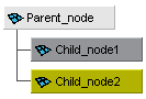
Selecting the parent node at the top of the hierarchy also selects the items contained in the hierarchy below. Selecting a child node lower in the hierarchy selects any child nodes that are lower in the hierarchy.
Hierarchies allow you to create complex structures with relationships between components. For example, when you animate a hierarchical model, you simply need to select and move the parent node of the hierarchy and the rest of the model (child nodes) also moves.
Regardless of whether you decide to animate the mechanical arm using FK or IK, or a combination of both methods on the same model, the best approach involves making the mechanical arm model into a hierarchical structure.
Creating a hierarchy for the mechanical arm ensures that:
Components of the hierarchy can be rotated as if they were one unit. A common pivot point is created at the parent node level. This allows the separate components to rotate as one unit based on their membership in the hierarchy. For example, if the mechanical arm’s base (parent node) is rotated, anything lower down the hierarchy, for example, the mechanical arm which is constructed of child nodes, will also rotate because of its membership and position in the hierarchy.
When a particular segment of the model is posed and keyframed, the components that are lower in the hierarchy are also posed and keyframed.
[4] Viewing hierarchies using the Hypergraph
In the following steps, you use the Hypergraph to view the hierarchy for the mechanical arm. The Hypergraph is a scene management editor that presents a graphical view of the scene hierarchy. It allows you to more easily create, understand, and manage the hierarchy of objects and nodes in your scene.
To view hierarchies using the Hypergraph
From the perspective view’s panel menu, select Panels > Layouts > Two Panes Stacked.
The workspace displays two panels stacked on top of each other with an identical perspective view of the scene.
In the lower panel, select Panels > Hypergraph Panel > Hypergraph Hierarchy.
The lower panel displays the Hypergraph.
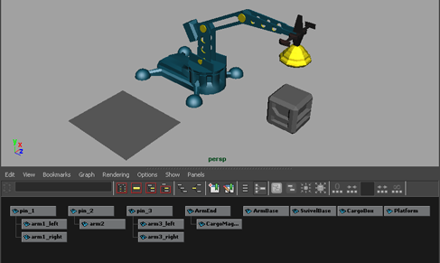
In the Hypergraph menu, select Graph > Scene Hierarchy.
If the menu item appears dimmed, it indicates that the Hypergraph is already displaying the scene hierarchy
In the Hypergraph menu, select View > Frame All to see all the components of your scene.
The boxes represent the nodes for the various items in the scene. Some items in the scene have already been parented into a hierarchy. This is indicated by the lines connecting some of the nodes. Selecting the nodes in the Hypergraph also selects the item in the scene view.
To select an item using the Hypergraph
In the Hypergraph, click each of the separate items in the hierarchy at the parent level to select them. At the same time, observe which objects become highlighted on the model in the perspective view.
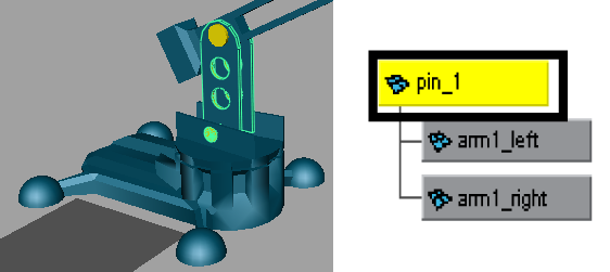
Hierarchies combine the various objects into discrete components for the mechanical arm, that is, the base, lower arm, middle arm, upper arm, and so on. If you select and rotate any of the parent nodes in the hierarchies, none of the other arm components follow because they are not combined into one unified hierarchy.
[5] Creating a skeleton hierarchy
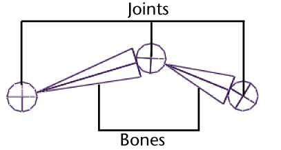
To link the various components of the mechanical arm into a hierarchy that can be posed, you need to create a skeleton. A skeleton is a hierarchy of joints that are connected together with bones.
In the scene, a joint represents a special type of node that gets created in a skeleton hierarchy. A joint acts as the parent node for any other joints that occur in the hierarchy below it. Each joint has a rotational pivot point associated with it. A bone is the visual representation used in the scene view to connect the joints and help visualize the joint chain.
A skeleton is similar to a skeleton in the real world in that it acts as the underlying structure for the surfaces to be attached. While you can view the skeleton with its bones and joints in the scene view, it does not appear in your rendered images. Its purpose is to assist you in setting up and posing your models and characters and to visualize the motion you want to achieve.
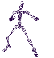
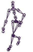
Skeletons are integral to the animation of any character or hierarchical model. Examples of characters that use skeletons are two and four legged animals. Skeletons are also useful for animating other organic components such as the tail of an animal, a tentacle of an octopus, or a snake.
In the following steps, you create a simple skeleton consisting of four joints that you combine with the mechanical arm model into a skeleton hierarchy, allowing you to pose and animate the model.
To create a skeleton for the mechanical arm
In the perspective view menu, select Panels > Orthographic > side.
The view updates to display the side view.
You need to view the components of the mechanical arm fully in the side view so you can draw the joints for the skeleton.
Resize the side view to a larger size by dragging the border between the side and Hypergraph panel views downwards.
In the side view menu, select Shading > Wireframe (Hotkey 4).
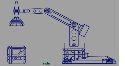
From the main menu, select Skeleton > Joint Tool >☐.
The Tool Settings window for the Joint Tool appears. The Joint Tool is used to create the joints and bones for a skeleton.
In the Joint Tool settings window, do the following:
- Click Reset Tool to set the tool to its default settings.
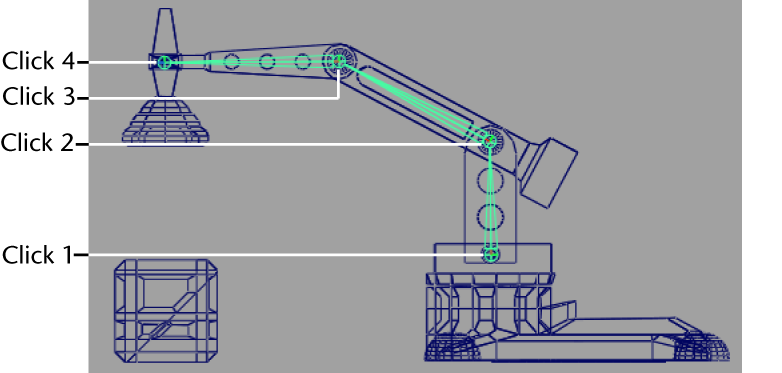
In the side view, starting from the base of the mechanical arm, do the following:
- Click in the center of each pivot pin on the mechanical arm to place four joints as shown in the image below.
Try to click as close to the center of each pivot pin as you can, as the rotation of the joints on the model will be based on the location of the joints on the skeleton. As you place the joints, a bone appears, connecting each joint. (Because the model lies along the YZ plane, the joints are created close to the center of each corresponding joint on the mechanical arm model.)
After you place the fourth joint, press Enter to indicate that the last joint has been placed.
In the Hypergraph, dolly the view to see the skeleton node hierarchy you just created. (It appears at the right side of the view.)
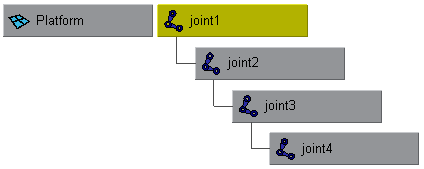
In the Hypergraph, select the joint1 node.
The entire skeleton becomes selected. Any rotations on this node also affect anything lower down the hierarchy.
Select joint2 (You can also press the down arrow on your keyboard to select further down the hierarchy).
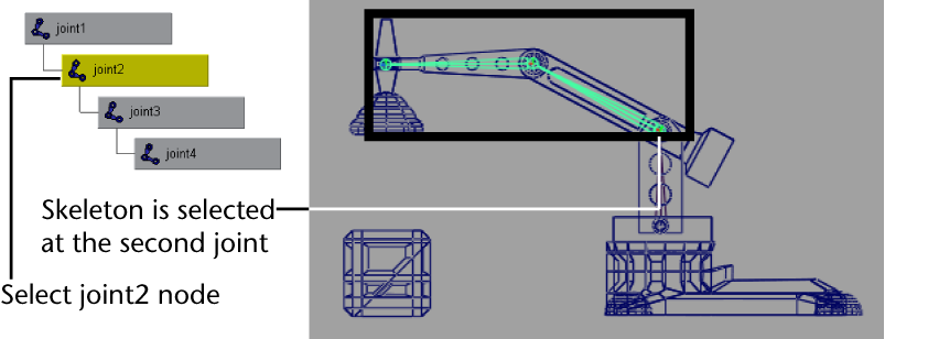
The skeleton is selected from joint2 downwards in the hierarchy. Any rotations that you make on this node affect only joint2 and nodes below joint2.
Once a skeletal hierarchy is created, the various surface components can be added to the hierarchy.
[6] Parenting a model into a skeleton hierarchy
Parenting is the term used when placing a node beneath another in a hierarchy so it becomes the child of the node above it (its parent) in the hierarchy.
In the following steps, you add the surfaces of the mechanical arm model into the skeleton hierarchy. This process links the models’ surfaces to the skeleton hierarchy making it possible to pose and animate the model like a real mechanical arm. Using the Hypergraph to select the nodes allows you to better visualize the process and the hierarchical relationships that result.
**NOTE:**The following parenting procedure works well for the mechanical arm (no organic bending or deformation occurs) and provides one technique for adding modeled objects to a skeletal hierarchy.
A more common technique for combining a character model into a skeleton hierarchy is referred to as skinning or binding. The Bind Skin tool combines the surface components and joints together into a hierarchy and also takes into account any deformations that may occur when a character bends or flexes (knees, waist, neck, elbows and so on). Maya provides a few methods for skinning. For a tutorial on skinning see the Smooth Skinning lesson in the Character Setup chapter in this guide.
To parent the mechanical arm into the skeleton
In the Hypergraph menu, select View > Frame All.
The Hypergraph displays all the nodes for the scene.
In the Hypergraph, select the node named ArmEnd and then Shift-select the node named joint4.
The order of selection is important. You want to select the child node first, and then Shift-select the item that will become the parent node second.
In the main menu, select Edit > Parent (Hotkey p).
In the Hypergraph, joint4 is now the parent node for the ArmEnd node in the skeleton hierarchy.
Repeat the parenting process for the following items:
pin3 is parented under joint3
pin2 is parented under joint2
pin1 is parented under joint1
Your new hierarchy should appear as shown in the diagram below.
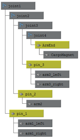
In the next steps, SwivelBase becomes the parent node for the new hierarchy so that the entire arm assembly swivels about the center of the base component.
In the Hypergraph, select the node named joint1 and then Shift-select the node named SwivelBase.
In the main menu, select Edit > Parent (Hotkey p).
In the side view menu, select Panels > Layouts > Two panes side by side.
The panels display in a side by side configuration.
Dolly the Hypergraph view as required to view the new hierarchy.
In the Hypergraph, select the node named SwivelBase.
In the side view, observe that both the mechanical arm model and the skeleton are selected.
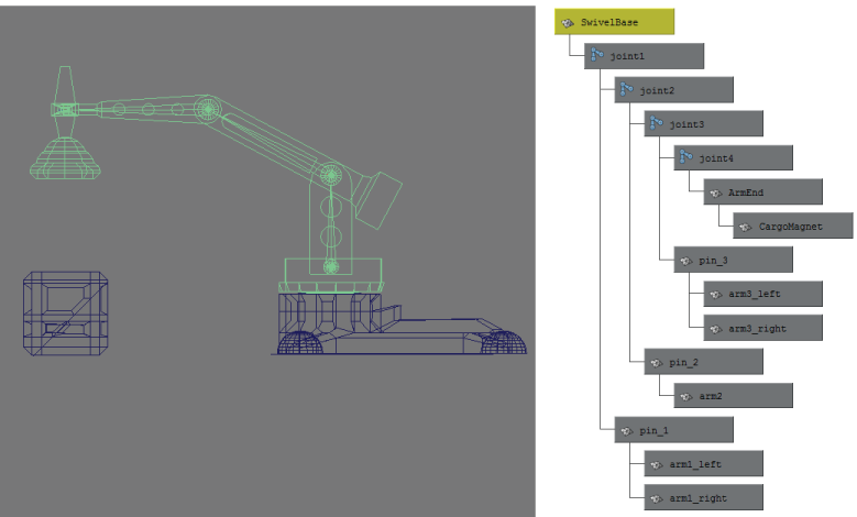
SwivelBase is the parent or root node for the hierarchy. If you rotate SwivelBase, everything else below that node (the entire arm with skeleton) rotates.
Select the node named joint3.
Observe that the last two components of the mechanical arm are selected. If you rotate joint3, only the components below that node in the hierarchy will be affected.
Select the node named pin2.
Observe that only one isolated segment of the model is selected. No other components or joints are selected when the pin2 node is selected. If you rotate the model at pin2, only the component at pin2 will rotate in isolation from the rest of the hierarchy because it is located lower in the hierarchy.
It is now possible to select and rotate the skeleton joints to pose the mechanical arm as a unit, and then set keyframes to animate it. Posing a character using joint rotations is referred to as Forward Kinematics (FK). FK allows for precise control when setting up a pose, but it can be a time consuming process to select and rotate each joint into the desired position.
When an animation is more focused on the goal of placing the end joint in a hierarchy in a particular position, (for example, a hand or a foot), it is more efficient to use Inverse Kinematics to pose the skeleton.
NOTE:
It’s not a simple matter to state that one technique or another is the only approach to achieving a desired result when animating in Maya. You must decide whether a particular technique works for a particular scenario based on the options it provides. A combination of animation techniques can be creatively used in a variety of ways.g IK to a skeleton hierarchy
[7] Applying IK to a skeleton hierarchy
IK allows you to control the joint rotations in a skeleton using an IK handle. You pose the skeleton by positioning the IK handle (usually located at the end extremity of the skeleton) and having the rotations for the other joints calculated automatically by the IK solver. In the steps that follow, you apply IK to the skeletal hierarchy.
To create an IK handle for the mechanical arm
From the main menu, select Skeleton > IK Handle Tool >☐.
The IK Handle Tool Settings window appears. When the mouse pointer is in the orthographic view its appearance changes to the tool's cross hair cursor .

In the IK Handle Tool Settings window, do the following:
Click Reset Tool to set the tool to its default settings.
In the IK Handle Settings, set Current Solver: Single-Chain Solver.
The Single-Chain Solver setting selects the IK Single Chain Solver. This solver ensures that the joints in the skeleton will lie along a single plane. This solver is well suited for the mechanical arm, because the arm doesn’t need to twist, unlike a real arm.
Working in the side view, starting from the base of the mechanical arm, do the following:
Click on the skeleton joint at the base of the mechanical arm.
Click on the skeleton joint at the tip of the mechanical arm. (The IK Tool is designed to attach to the joints closest to your selection point.)
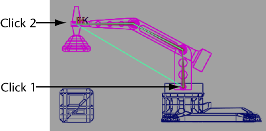
In the side view, the IK handle is drawn as a line from the start and end joints of the IK chain.
In the Hypergraph menu, select View > Frame All.
In the Hypergraph, two new nodes appear in the hierarchy that represent the IK chain: an IK Handle node and an end effector node.
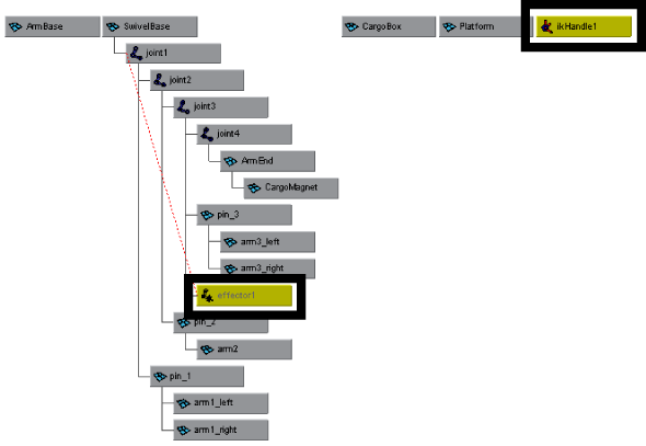
In the Hypergraph, select the node named ikHandle1.
The IK Handle (in combination with the end effector) is used by the IK solver to calculate the rotation of the joints in the IK chain. By default, the IK Handle is located at the last joint of the IK chain in the scene view.
Select the Move Tool from the Toolbox, and drag the Move Tool’s Z axis manipulator (blue arrow) to reposition the mechanical arm.
When you drag the manipulator, the skeleton and mechanical arm model are repositioned.
Reset the mechanical arm to its previous position by selecting Edit > Undo until the mechanical arm is positioned into its previous orientation.
NOTE:When using the Undo feature, do not undo so many times that you inadvertently undo the IK handle you’ve just created.
The next steps describe how to manipulate the IK Handle using a control object.
[8] Creating a control object for an IK system
Using the IK Handle to pose an IK chain is generally not a good practice. The IK Handle can be challenging to select in the scene view, especially when it’s grouped into a hierarchy that includes a skeleton and other surface components. A better practice is to create a control object.
You create a control object to select and manipulate an IK system instead of directly using the IK Handle. You can create a control object with a curve or a locator, which are often used because they don’t appear in the rendered image.
The control object controls the movement of the IK Handle using a constraint. You can constrain the position, orientation, or scale of an object to other objects using constraints.
To create a control object:
Create and position the control object in the scene view.
Name the node for the control object in the Hypergraph.
Freeze transformations for the control object.
Label the control object in the scene view.
Constrain the IK Handle to the control object.
To create a control object using a locator
From the main menu, select Create > Locator.
A three-dimensional cross is created at the origin in the scene view.
Select the Move Tool from the Toolbox.
In the side view, reposition the locator slightly above and in front of the end of the mechanical arm as shown in the image below.
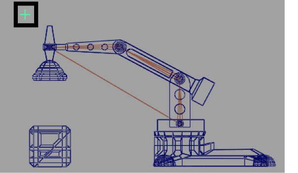
To easily identify the locator as a control object in the Hypergraph, rename the locator.
To rename the control object using the Hypergraph
In the Hypergraph, right-click the node named locator1. Choose Rename from the pop-up menu that appears.
In the Rename Node window that appears, type the name ArmControl and press Enter to save the name for the locator.
Before you constrain the IK handle to the control object, you need to freeze the transformations for the control object. Freeze Transformations zeros the transformations for an object without changing the position of the object. This is another good practice; If it becomes necessary to reset the arm to its default position, you can set the transformation on the control object to zero, and the arm will return to this default pose.
To freeze the transformations for the control object
In the Hypergraph, select the node named ArmControl.
The control object is selected in the scene view.
In the main menu, select Modify > Freeze Transformations >☐.
In the Freeze Transformation Options window do the following:
Select Edit > Reset Settings to set the tool to its default settings.
Click Freeze Transform.
The transformations for ArmControl are set to zero. From this point onwards, you can reset its position to this location by zeroing its translations in the Channel Box.
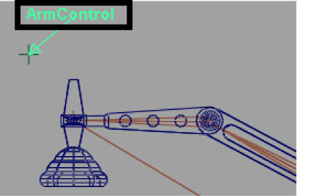
To easily identify the locator as the control object in the scene view, label the control object using an annotation. An annotation is a text label that can be set to point at the labeled item. Annotations are useful because they always face the viewer, regardless of the orientation of the model in the scene view.
To label the control object in the scene view
In the Hypergraph, select the ArmControl node.
In the main menu, select Create > Annotation.
In the Annotation Node window that appears, type ArmControl and click OK.
In the scene view, the word ArmControl appears near the locator/control object. In the Hypergraph, two new nodes appear in a hierarchy beneath ArmControl.
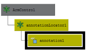
With the annotation1 still selected, select the Move Tool.
In the side view, drag only the annotation so it appears slightly offset from the locator object as shown below.
The annotation displays in any scene view so you can easily identify the control object for selection.
To simplify the display of the Arm Control node
In the Hypergraph, right-click the ArmControl node. Choose Collapse from the pop-up menu. (You can also double-click a node to collapse or expand the hierarchy below it.)
The ArmControl node appears as a single node instead of the previous three node hierarchy. The small arrowhead on the lower left-hand corner of the node indicates that the node is collapsed.

The control object must be linked to the IK Handle to control the IK Handle.
[9] Constraining an IK system
You can constrain the IK Handle to the control object (ArmControl) using a point constraint. A point constraint allows the transformation attributes of one object to be controlled by the transformations of another object. For example, you select and position ArmControl without having to touch the IK Handle. You also set the constraint so ArmControl maintains the current distance (offset) from the IK Handle. The offset ensures that the constrained IK handle doesn’t move to the same position as the control object.
To constrain the IK Handle to the control object
In the Hypergraph, select the ArmControl node and then Shift-select the ikHandle1 node.
The order of selection when applying a constraint is important: you must select the constraining object first, and the item to be constrained second.
In the main menu, select Constrain > Point >☐.
The Point Constraint Options window appears.
In the Point Constraint Options window, do the following:
Select Edit > Reset Settings to set the tool to its default settings.
Turn on the Maintain Offset setting.
Click the Add button.
The IK handle is constrained to the control object. In the Hypergraph, a constraint node is created beneath the ikHandle1 node.
In the Hypergraph, select only the ArmControl node.
In the Toolbox, select the Move Tool.
In the side view, drag the manipulator to reposition the control object. (Experiment with a few different positions in the side view only.)
When you drag the manipulator, the control object moves, which in turn moves the IKHandle. Because the IK handle controls the skeleton and the mechanical arm model, they also move. The offset between the control object and the IK Handle is maintained.
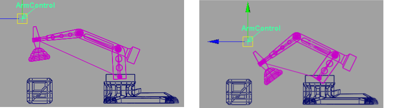
The Cargo Magnet does not continuously point downwards when rotated. Its orientation is based on the rotation it had in its original position.
The mechanical arm will be easier to pose if you set Cargo Magnet to be oriented downwards towards the floor of the scene regardless of the orientation of the other components of the arm.
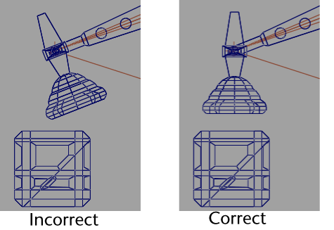
You make CargoMagnet point downwards using an orient constraint. An orient constraint constrains the orientation (rotation) of the X, Y, and Z axes of one object to match those of the constraining (target) object.
In the next steps, you reset the position of the mechanical arm to its default position, and then apply an orient constraint to the last joint in the IK system so that its orientation matches the control object. The effect is that CargoMagnet points downwards regardless of any other movement in the scene.
To set the IK system to its default position
In the Hypergraph, select the ArmControl node.
Open the Channel Box by clicking the Show/Hide Channel Box icon

.
In the Channel Box, set the X, Y, and Z transformations for ArmControl to 0.
Zeroing the transformations on ArmControl resets the mechanical arm to its home position because of the freeze transformations step you performed in the previous section.
Close the Channel Box by clicking the Show/Hide Channel Box icon.
To apply an orient constraint for the IK system
In the Hypergraph menu, select View > Frame All.
The Hypergraph displays all the nodes in the scene.
In the Hypergraph, select ArmControl and then Shift-select the node named joint4. (You may need to dolly and track the Hypergraph view to view these nodes.)
In the main menu bar, select Constrain > Orient >☐.
In the Orient Constraint Options window, do the following:
Select Edit > Reset Settings to set the tool to the default settings.
Click the Add button.
Joint4 is constrained to have the same orientation as the control object. In the Hypergraph, the constraint node is created below the joint4 node in the hierarchy.
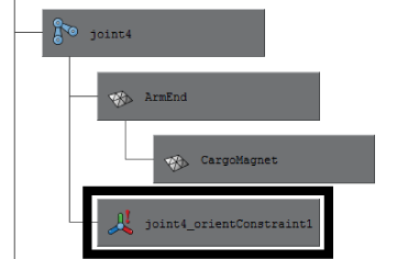
With only the ArmControl node selected, use the Move Tool to reposition ArmControl in the side view.
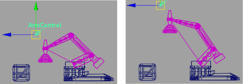
CargoMagnet maintains an orientation facing the floor of the scene regardless of how the mechanical arm is positioned in the side view.
In the next section, you learn how to limit the range of movement for the IK system.
[10] Limiting the range of motion of an IK system
It’s possible to move ArmControl so that the mechanical arm fully extends to a straight position or orients itself to other positions that you don’t necessarily want.
You can limit the range of motion of the arm to ensure that the IK system poses in a predictable manner. In the following section, you limit the motion for the IK system as follows:
Lock the translation of the control object (ArmControl) so that it can only move in Y and Z. By locking the X channel so it cannot be selected or modified, the arm will not be able to move from side to side.
Lock the rotations on the swiveling base for the arm so it only rotates about its Y axis, and not about its X or Z axes.
Limit the translations for the Arm Control so the mechanical arm cannot fully extend to a straightened position.
To lock the Translate X channel for ArmControl
In the Hypergraph, select the ArmControl node.
Open the Channel Box to view the transform channels for ArmControl.
Set all Translate or Rotate channels to 0, if they are not already.
In the Channel Box, select the Translate X channel by clicking on its name.
Right click on the word Translate X.
A drop-down menu appears.
From the drop-down menu, choose Lock Selected.
The numerical field for Translate X is dimmed indicating that the channel is locked. If you try to move ArmControl in X, it will not be possible unless you unlock the Translate X channel.
To lock the Rotate X and Z channels for SwivelBase
In the Hypergraph, select only the SwivelBase node.
Open the Channel Box to view the rotation channels for SwivelBase.
Set all Translate or Rotate channels to 0, if they are not already.
In the Channel Box, select the Rotate X and Rotate Z channels by Ctrl-clicking on their names.
Right-click on either of the selected names and select Lock Selected from the drop-down menu that appears.
To confirm that the Rotate X & Z channels are locked
In the Hypergraph, ensure only the SwivelBase node is selected.
From the side view's panel menu, select Panels > Orthographic > top.
In the panel menu, select Shading > Smooth Shade All.
Dolly the top view so you can fully view the mechanical arm as shown below.
Using the Channel Box, rotate SwivelBase by typing 45 in the Rotate Y channel and pressing Enter.
SwivelBase rotates in the view but the mechanical arm does not rotate.
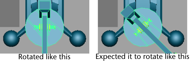
You first might think something is wrong because SwivelBase and all of the arm’s skeletons and surfaces are parented into the same hierarchy.
If you discover that something doesn’t work in the manner you originally anticipated when setting up an IK system, it’s useful to stop and diagnose why something is working the way it is (or not working the way it should). In that way you can retrace your actions to determine where the problem resides.
In this example, ArmControl and IK Handle are not parented into the SwivelBase hierarchy.

Because ArmControl and IK Handle control the movements of the mechanical arm, they must be parented into the SwivelBase hierarchy in order for the arm to rotate when SwivelBase is rotated.
To parent the IK Handle into the skeleton hierarchy
In the Hypergraph, select the SwivelBase node.
In the Channel Box, reset the Rotate Y channel for SwivelBase to 0.
Setting any previous transformations to zero is necessary before parenting the IK Handle beneath SwivelBase in the hierarchy.
Unselect the SwivelBase node before performing the following steps.
In the Hypergraph menu, select View > Frame All.
The Hypergraph displays all the nodes for the scene.
In the Hypergraph, Shift-select the nodes named ikHandle1, ArmControl, and SwivelBase.
The order of selection is important. You want to Shift-select the items that will be the child nodes first, and then Shift-select the item that will be the parent node last.
In the main menu, select Edit > Parent (Hotkey p).
In the Hypergraph, IKHandle and ArmControl are now child nodes for the SwivelBase node in the skeleton hierarchy.
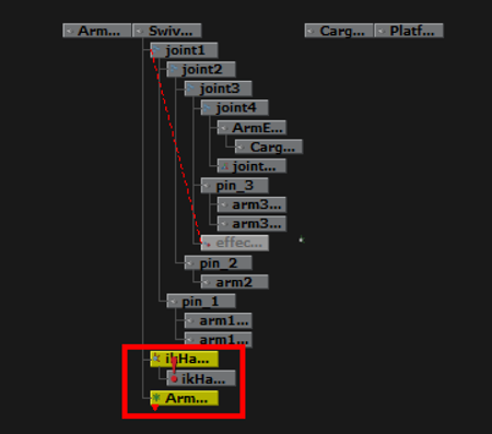
In the Hypergraph, select only SwivelBase.
Using the Channel Box, set Rotate Y for SwivelBase to 45.
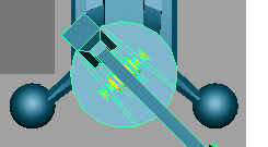
When SwivelBase is rotated, the mechanical arm rotates because of its relationship within the hierarchy.
Reset the Rotate Y value for SwivelBase back to 0.
Finally, you want to limit how far Arm Control can translate away from the base of the model so the arm does not extend to a fully straightened position.
To determine the settings for the translation limits you need to examine the position of the mechanical arm in various positions while simultaneously viewing the translation values in the Channel Box.
To determine translation limits for the Arm Control
In the Hypergraph, select ArmControl.
Ensure the Channel Box is open so you can view the translate channels for ArmControl.
In the view, select Panels > Orthographic > side.
Press 4 to return to wireframe mode.
Dolly the side view so you can fully view the mechanical arm.
Select the Move Tool.
In the side view, middle-click and drag the mouse diagonally until the mechanical arm is fully extended as shown below.
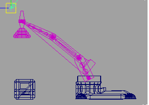
In the Channel Box, observe the number that displays in the Translate Y and Z channels.
When the arm is diagonally articulated above the cargo box, it is almost fully extended when the translation values are roughly as follows:
Translate Y: 7.5
Translate Z: 1
In the side view, press the middle mouse button and drag the mouse diagonally until the mechanical arm is almost fully compressed as shown below.
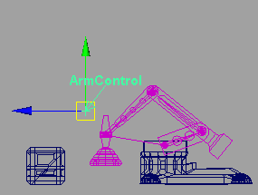
In the Channel Box, observe the numbers that display in the Translate Y and Z channels.
When the arm is articulated to a compressed pose, the translation values are roughly as follows:
Translate Y: -13
Translate Z: -13
These minimum and maximum values will be used in the steps that follow as the minimum and maximum translation limits for the ArmControl.
To set translation limits for the Arm Control
In the Hypergraph, select the ArmControl node.
Open the Attribute Editor (Window > Attribute Editor or click on the Show/Hide Attribute Editor icon

on the Status Line).
The Attribute Editor displays the nodes associated with Arm Control.
In the Attribute Editor, click the ArmControl tab.
If the ArmControl tab is not visible, use the left and right scrolls arrows to scroll the view sideways to view it.
In the Attribute Editor, expand the Limit Information attributes, and then the Translate attributes.
In the Translate attributes, click the Trans Limit Y and Trans Limit Z check boxes for both the Min and Max values, then set the following values:
Trans Limit Y (Min): -13
Trans Limit Y (Max): 7.5
Trans Limit Z (Min): -13
Trans Limit Z (Max): 1
Hide the Attribute Editor.
Select ArmControl.
In the side view, move ArmControl to test the range of movement for the IK system.
The mechanical arm moves with a limited range of motion.
[11] Simplifying the display of a hierarchy
The number of nodes in the IK system’s hierarchy at this point may appear a bit overwhelming, but it allows the posing of the mechanical arm to be efficient and effective. You can simplify the display of the nodes by collapsing portions of the hierarchy.
To collapse the display of the hierarchy
In the Hypergraph, right-click on joint1, and choose Collapse from the pop-up menu.
The child nodes below joint1 disappear, simplifying the display of the hierarchy. The small arrowhead on the corner of the joint1 node indicates that a hierarchy exists below joint1. If you later need to view or select these nodes you can expand them again.
Collapse the ArmControl and IKHandle nodes.
The display of the hierarchy is simplified as shown below.
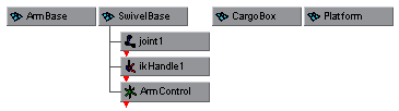
The IK system is now rigged and ready for animation.
[12] Applying parent constraints on an IK system
To animate the cargo box so that it is picked up by the mechanical arm you need a method of constraining the cargo box to the mechanical arm so that it moves with the arm at specific times in the animation. This is accomplished using a parent constraint.
When a parent constraint is applied to an object, the constrained object behaves as if it were a child node of the constraining object.
An object can have multiple constraints applied to it. The influence each constraint has on the object can be changed by modifying the weight attribute for the parent constraint. The weight attribute is an animatable parameter and can be set to be on or off at specific frames.
In this lesson, the cargo box is constrained to both the ArmControl and the Platform on the floor. By animating the weight attributes for these two parent constraints, the cargo box will move from one location to another depending on which constraint is influencing it at specific times in the animation.
To set up the parent constraints you need to position the constrained object at the locations where the influence will begin or end, and then set the parent constraints.
To set parent constraints for the cargo box
From the side view's panel menu, select Shading > Smooth Shade All.
From the side view's panel menu, select Panels > Perspective > persp.
In the Hypergraph, select ArmControl.
In the Channel Box, set the Translate Y and Translate Z values as follows:
Translate Y: -9
Translate Z: 0
The arm is repositioned so that the cargo magnet is directly above the cargo box as shown below. Track, tumble, or dolly the view if required so you can see the mechanical arm unobstructed.
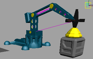
In the Hypergraph, with ArmControl still selected, Shift-select the CargoBox node.
The order of selection is important when you apply constraints. You must select the constraining object first, and the item to be constrained second.
In the main menu, select Constrain > Parent >☐.
In the Parent Constraint Options window, do the following:
Select Edit > Reset Settings to set the tool to its default settings.
Click the Add button.
CargoBox is constrained to ControlArm. A new constraint node has been created below the CargoBox node in the Hypergraph. If you reposition the mechanical arm, CargoBox moves with it because of the constraint that is now applied.
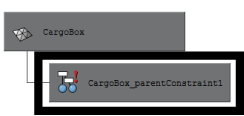
In the Hypergraph, select only SwivelBase.
In the Channel Box, set the Rotate Y value for SwivelBase as follows:
- Rotate Y: -100
The mechanical arm and the cargo box are positioned as shown below.
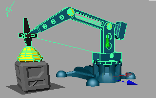
In the Hypergraph, select Platform and then Shift-select the CargoBox node.
In the main menu, select Constrain > Parent.
CargoBox is constrained to Platform. This is the second constraint for the CargoBox.
In the Hypergraph, select only CargoBox.
In the Channel Box, view the parent constraints for CargoBox.
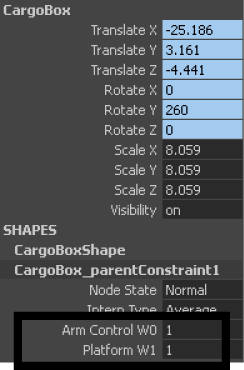
CargoBox has two parent constraints applied to it: Arm Control and Platform. In the Channel Box, the numerical settings beside ArmControl W0 and Platform W1 represent the influence weight each parent constraint has on CargoBox. At this point, each influence weight is set to a value of 1. If you move the mechanical arm, the cargo box will move somewhere between its first and second position. This occurs because each constraint has equal influence on the cargo box at this point.
Before you can animate the objects in the scene, you also need to reset the default weight values for each constraint, so that one parent constraint has full influence on CargoBox when the other does not.
To set the weighting for the parent constraints
In the Hypergraph, select only CargoBox.
In the Channel Box, set the following:
- Platform W1: 0
Select only SwivelBase.
In the Channel Box, set the Rotate Y value to 0.
The mechanical arm and cargo box are rotated back.
In the Hypergraph, select only CargoBox.
In the main menu, select Constrain > Set Rest Position.
Setting a rest position for CargoBox sets a position for the cargo box when no constraints are acting upon it. If the rest position is not set, CargoBox will be repositioned to the second constraint position.
In the Channel Box, set the following:
- ArmControl W0: 0
At this point, both parent constraints are set to have no influence on the cargo box because their weight attributes are set to zero. When you animate the components in the scene, the weight attributes for the parent constraints will be set and keyframed depending on which constraining object (Arm or Platform) is required to have full influence.
In the next steps, you plan the action for animation of the IK system.
[13] Planning an animation for an IK system
Now that the mechanical arm and cargo box are fully set up for animation it’s a simple matter to pose the arm and set keyframes. Prior to setting any keyframes you should take a few moments to plan the action for the scene.
Planning the action usually involves sketching a simple storyboard, and writing out a brief timeline for the action for each component. In this lesson we’ve provided a simple version for you. The basic premise for the action is as follows:
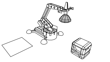
The cargo box is positioned directly in front of the mechanical arm.
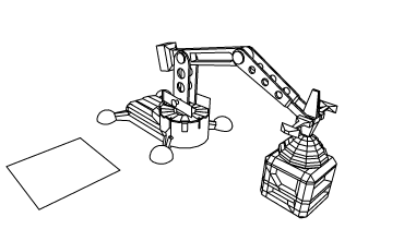
The mechanical arm extends, and positions the cargo magnet to be directly touching the top of the cargo box.
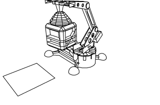
The mechanical arm extends upwards, lifting the cargo box, and rotates to the side.
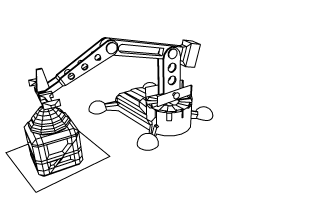
The mechanical arm lowers the box, placing it in a new position.
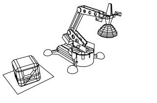
The mechanical arm extends upwards, leaves the cargo box in the new location, and rotates back to its original position.
The table below breaks down the action indicating what action occurs for each object at the specified keyframes.
| Frame | Mechanical Arm | Cargo Box |
| 1 | Collapsed position | Initial position |
| 30 | Vertically extended position | Initial position |
| 60 | Vertically lowered so that cargo magnet is positioned on top of cargo box | Initial position |
| 80 | Vertically lifted to extended position with cargo box | Cargo box lifted with mechanical arm |
| 100 | SwivelBase rotated along with arm to side | Cargo box repositioned along with mechanical arm |
| 120 | Vertically lowered along with cargo box to second position above surface | Cargo box is lowered along with mechanical arm to second position |
| 140 | Vertically lifted to extended position | Second position |
| 160 | SwivelBase rotated with arm to original position | Second position |
| 180 | Collapsed position | Second position |
To pose the mechanical arm you select either the ArmControl or SwivelBase nodes and set a keyframe depending on which component you want to pose:
ArmControl controls the movement of the mechanical arm.
SwivelBase controls the rotation of the arm.
CargoBox’s position is based on the parent constraint weights.
[14] Animating an IK system
The animation sequence occurs over a 180 frame period. Before you begin to set keyframes you set the playback range in the Time Slider.
To set the playback range in the Time Slider
In the Animation Time and Range Slider, set the following start and end times for the animation:
Playback Start Time: 1
Playback End Time: 180

To simplify the keyframe workflow, you first set keyframes for the mechanical arm, and then set keyframes for the weight attributes of each parent constraint for the cargo box.
To set keyframes for the mechanical arm
In the Time Slider, go to frame 1.
Select only ArmControl.
In the Channel Box, set the following values:
Translate Y: 0
Translate Z: -13
From the main menu, select Animate > Set Key.
To set the remaining keyframes for the arm and the swivel base, use the table below as a guide, and set the attributes in the following order:
Set the frame using the Time Slider.
Set the attributes for the object in the Channel Box.
Set the keyframe (Animate > Set Key).NOTE:
Don’t be concerned if the list of keyframes indicates to set a key twice for the same position over two frames. This is necessary to animate the parent constraint weights over a period of one frame.
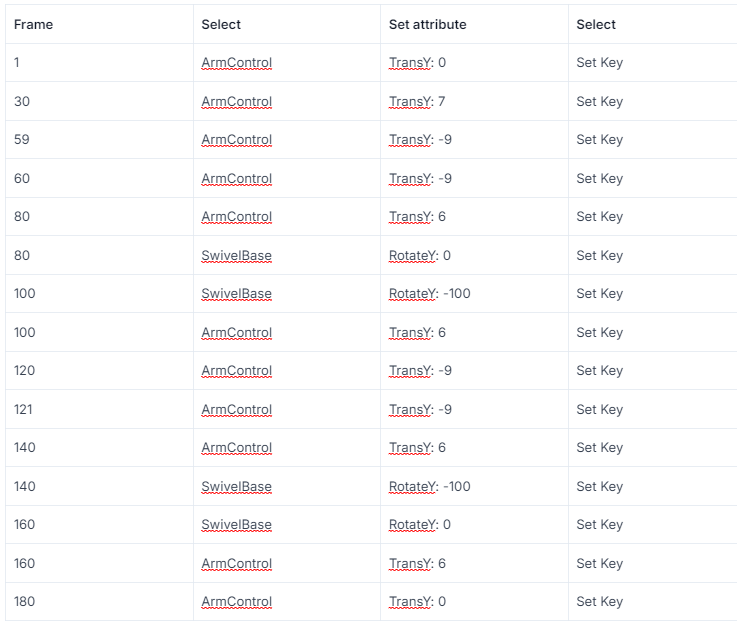
Once the keyframes for the mechanical arm are set you can use the playback controls to playback the motion for the mechanical arm.
To playback the animation using the playback controls
Click play on the Time Slider playback controls to play the animation.
The mechanical arm animates over 180 frames. The cargo box does not move because the weight attributes for the parent constraints are set to zero and have not yet been set for the animation.
Click stop on the Time Slider playback controls to stop the playback.
In the next steps, you set keyframes for the parent constraint weight attributes so the cargo box is lifted, moved, and placed in the second location. You set keys for the weight attributes on the parent constraint node.
To set keyframes for the parent constraint weights
In the Time Slider, go to frame 1.
In the Hypergraph, select the node for the parent constraint directly below CargoBox.
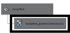
In the Channel Box, set the following values (if they are not set already):
ArmControl W0: 0
Platform W1: 0
In the Channel Box, select the ArmControl and Platform channels by shift-clicking on the names.
Right-click on either one of the selected names.
A drop-down list appears.
From the drop-down list, choose Key Selected.
Key Selected sets a keyframe for the selected attributes only.
To set the remaining keyframes for the parent constraint weights, use the table below as a guide, keeping in mind that you set the attributes in the following order:
Set the frame using the Time Slider.
Set the parent constraint attributes in the Channel Box.
Right-click on the selected names and select Key Selected.
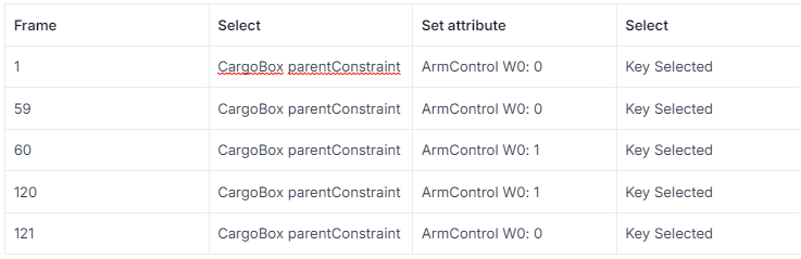
To playback the animation using the playback controls
Click play on the Time Slider playback controls to play back the animation.
The mechanical arm moves through the motion of the animation and picks up and moves the cargo box to the new location.
Click stop on the Time Slider playback controls to stop the playback.
You have completed this lesson.
[15] Beyond the lesson
In this lesson, you completed the animation of a mechanical arm model that picked up and moved a cargo box. You learned how to:
Construct a model hierarchy to provide relationships between the components for posing and keyframing.
Construct a single chain skeleton to pose the arm model using Inverse Kinematics.
It is common to create characters with multiple joint chains. For example, two and four-legged characters would use multiple joint chain skeletons to assist with posing their hierarchical structure. For a tutorial on creating a multiple chain skeleton see Lesson 1: Skeletons and Kinematics (Introduction).
Parent the components of the mechanical arm model into the skeleton hierarchy.
Parenting is one method for combining a model into a skeleton hierarchy. When using characters that have bending or deforming features a more common technique is to use Skin > Bind Skin. For a tutorial on smooth skinning see Lesson 2: Smooth Skinning (Introduction).
An easy method to parent one node to another using the Hypergraph is to drag one node over top of the other using your middle mouse button.
Create an IK system with a control object for manipulation.
It is very common to create characters with multiple joint chains and multiple IK handles to control them. Control objects simplify the selection and posing of the character.
Use three types of constraints (Point, Orient, Parent) to control components of the IK system and other components in the scene.
Constraints are useful for animating the attributes of one object based on the attributes of another. Other types of constraints not covered in this lesson include aim and scale constraints.
Using the parent constraint, the platform could also be animated to move the cargo box as if it were on an elevator, or a conveyor belt.
Apply limits to the movement of the IK system.
In this lesson, you constrained the translation of the control object in order to constrain the movement of the IK. It is not recommended that you set limits on the rotation of an IK system as it limits how the solver calculates the position of the joints.
Although not covered in this lesson, it is possible to simplify the display of attributes in the Channel Box so that only the animatable attributes associated with a character are displayed.
Pose and set keyframes for an IK system.